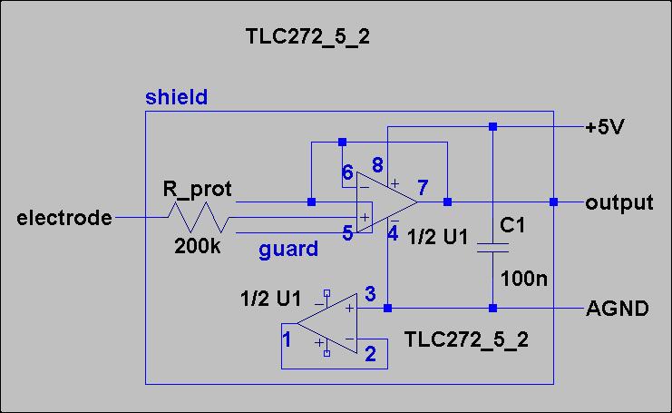
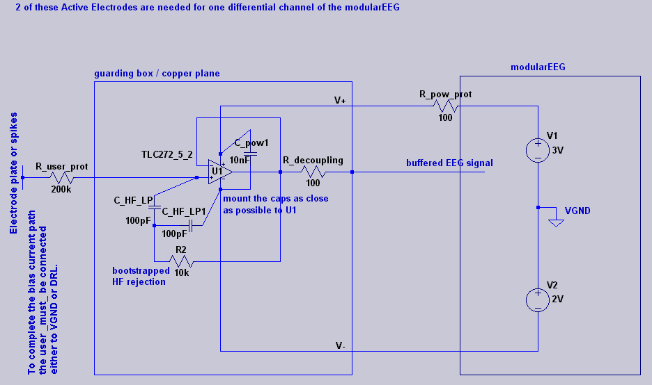
I am trying to build some active electrodes for my modularEEG along the lines of the V2 prototype described by Jarek Foltynski here. I am using the modified circuit diagram suggested by Joerg Hansmann (second below):
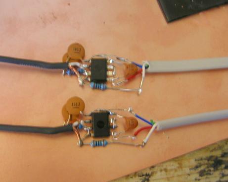
I am wiring up the chip (TLC272CP) to the components without a board, working with it upside-down with the legs flattened out. I am also hoping to encapsulate it all in potting compound somehow later on if possible:
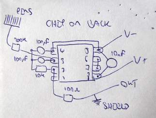
I am using guarding (see the TLC272 datasheet page 17 for some details on guarding), with the amplifier output used directly as a guard on the input wire leading to the electrode. However, there is a small part of the input wire that is unguarded, between the shielded cable and the chip pin 3 input, where the capacitor joins it. Hopefully this won't be a problem. This area was wrapped in insulating tape later.
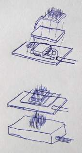
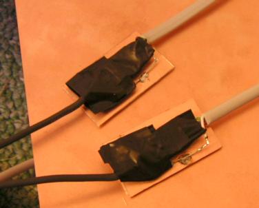
I am also using copper-plated board as a kind of sandwich to provide shielding. The output signal after the 100 ohm resistor is connected to the shield as specified in Joerg's diagram:
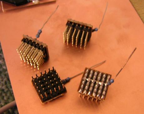
Here are my electrodes. I am trying the gold-plated pin idea, which should go through hair better to make a connection to the scalp.
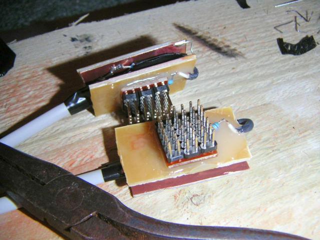
Result so far, with electrode glued to upper sandwich layer with epoxy. Ideally I'd still like to encapsulate all of this somehow, preferably up to the base of the pins:
Main modularEEG box from much earlier. This is huge because I was leaving room for another couple of analogue boards, just in case. 12 of the 3.5mm sockets are no longer in use because the electrode inputs are now coming through the 7-pin DIN sockets on the top. The remaining two provide VGND and DRL. The 7-PIN DIN sockets are wired up: V-(==AGND), calib1, inp1, VGND, inp2, calib2, V+(==5V). VGND is only used for shielding up to the point where the cable splits to the two active electrodes. The black dummy plugs plugged in connect up the calibration inputs for testing:
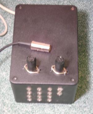
Note that inside the box, the power lines for the DIN sockets are picked up from the pin-connector between the analogue and digital boards, or nearby. The analogue supply rails are used, not the digital ones. The analogue power rails are available on pins 1, 3 and 5, which give +5V, +2V and 0V (Vcc, VGND, AGND on the analogue schematic; or V+, VGND, V- in my list above). Note also that a 100 ohm power-protection resistor (as shown on Joerg's diagram) should be connected between the board and each DIN socket V+ (one resistor for each DIN socket) to avoiding damaging the board if you accidentally short together V+ and V- in your cable.
So far so good ...
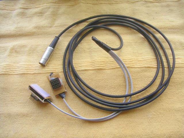
This is what the completed lead looks like right now. Note that I have added velcro hooks to the back of the electrodes, and soldered some pins between the boards to hold them firm. These would have to be cut or unsoldered if I ever needed to fix anything.
I don't have a proper harness yet for wearing these on my head, but
here is an example recording done with the electrodes under a soft
hat. The electrodes were both on the right side, one over the
parietal frontal area (towards the front at
the top, above the hairline) and the other over the occipital area (at
the back of the skull). Alpha waves can be clearly seen when I closed
my eyes here:
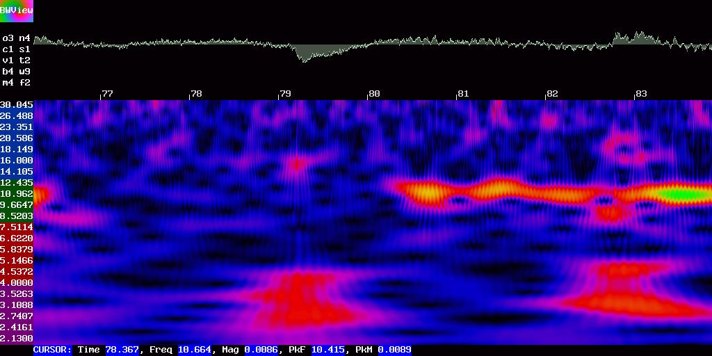
Note that the horizontal scale above is 2 samples per pixel. This was only a quick recording, but anyway here is the raw modularEEG-format serial-dump file in a ZIP: dump.zip.